RedBrick AI is designed for native medical image viewing and annotation, supporting all radiology modalities. The platform supports X-ray, CT, MRI, Ultrasound, and other 2D, 3D, and video modalities.Documentation Index
Fetch the complete documentation index at: https://docs.redbrickai.com/llms.txt
Use this file to discover all available pages before exploring further.
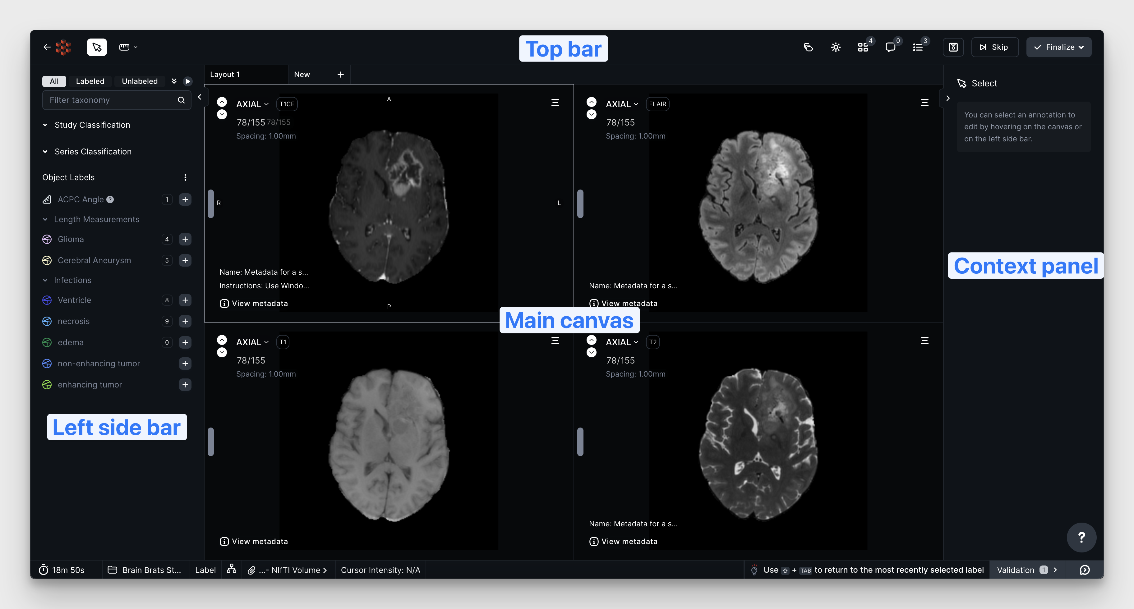
- Left Sidebar - where you create, edit, and interact with annotations and attributes.
- Top Bar - contains Task-level actions such as task submission and saving and the environment settings (Windowing, Layout), Version Explorer, Segmentation Tools, and Quick Measurement Tools.
- Context Panel - shows additional information and settings for any currently selected tool(s) or open panels.
- Main Canvas - where you interact with your images and apply your annotations to your images/volumes.
Viewing and Navigating Your Volume
Interacting with your images in RedBrick AI is similar to other medical imaging and PACS viewers. This section covers the basic shortcuts and functions for navigating through a volume.You can find a comprehensive list of shortcuts by clicking on the (?) Help button in the bottom-left of the screen.
Changing Slices
- Scroll: Scroll over any of the viewports.
- UI: Use the viewport’s slider or up/down slice buttons.
- Shortcut: Use the
up arrowanddown arrowkeyboard shortcuts on the selected viewport. - Quick slice change: Hold
alt/optionandleft clickdragto quickly change slices.
Zoom and Pan
- Zoom: Hold
ctrlandscrollto zoom. - Quick zoom: Hold
ctrlandright clickdragfor a quick zoom. - Pan: Hold
shiftandleft clickdragto pan.
Windowing
- UI: Adjust windowing on the context panel by activating it from the top bar.
- Shortcut: Hold
CTRLandleft clickdragvertically to adjust the Windowing Level and horizontally to adjust the Windowing Width.
3D Model Viewing
- Rotate:
Left clickdragto rotate the volume in 3D. - Rotate fixed plane: Hold
ctrlandleft clickdragto rotate the model fixed in the plane. - Pan: Hold
shiftandleft clickdragto pan. - Zoom: Hold
ctrl/cmdandscrollto zoom.
- Rendering preset: adjusts the photorealistic rendering style.
- Shift: adjusts the volume rendering transfer function to modify the rendering.
- Maximum opacity: sets the maximum voxel opacity of the rendered image.
Crosshairs, 3D Double-Click Jump, and Oblique Planes
Crosshairs will synchronize multiple projections of a single volume. Oblique planes allow you to view a non-orthogonal view of a volume.Crosshairs will only be available on 3D modalities. Also, you must have multiple orthogonal projections in your viewport (for example, Axial and Sagittal) for crosshairs to appear.
Crosshairs
- Activate: From the top bar or by pressing
c. - Adjust crosshairs:
Left clickdragon a crosshair line to move and synchronize the intersection point across views. - Deactivate: From the top bar or by pressing
esc. By default, deactivated crosshairs will still be shown on the canvas and can be reactivated by selecting them. To hide deactivated crosshairs, presscmd/ctrlshiftc.
3D Crosshairs
When Crosshairs is active and you have a 3D viewport open for the same series, the 3D viewport displays crosshair intersection guides that update as you adjust the 2D views.3D Double-Click Jump
On a 3D viewport, double clicking a segmentation will adjust the associated 2D views into focus at that point. This can be used to quickly find a location from the 3D view on the 2D viewports.Oblique Planes
- Activate:
Right clickon any viewport, then selectactivate oblique. This will enable an oblique plane for just the selected projection. - Usage: The oblique plane crosshair for each viewport will be color-coded. For example, the Sagittal oblique plane is purple in the video below. Rotating the purple crosshair creates an oblique plane on the Sagittal view.
Maximum and Minimum Intensity Projection (MIP)
Maximum Intensity Projection (MIP) displays the highest intensity values in a 3D image along a viewing axis, useful for highlighting bright structures like blood vessels. Minimum Intensity Projection shows the lowest values, useful for revealing dark structures like airways.You can only view MIP along the imaging axis for any volume.
Managing Your Layout
RedBrick AI’s viewer can be customized to display studies and series in a huge range of configurations, either manually or by using hanging protocols to display single or multiple series.Changing Layout and Displaying Series
- Change layout grid: Each modality has a default layout grid which can be modified from the layout grid on the top bar. The viewer supports everything between 1x1 and 3x3, showing a maximum of 9 views.
-
Displaying series: You can customize what is shown in each viewport; this can be any 2D or 3D view.
-
Drag and drop: You can drag and drop any series or projection from the layout context panel to a target viewport.
-
Viewport selector: You can use the dropdown on any viewport to cycle between projections of that series.
-
Quick change: You can hover over the thumbnails on the layout context panel to directly place the view in the corresponding layout position.
-
Drag and drop: You can drag and drop any series or projection from the layout context panel to a target viewport.
-
Maximize and minimize view: When you have more than 2 views displayed, you can maximize 1 viewport so that it’s larger than the rest. Pressing
enterwill expand the currently selected viewport. Alternatively, you canright clickand selectmaximize viewporton the layout menu.\
-
Full-screen mode: Press
fto enter full-screen mode for distraction-free annotation.
Multiplanar Reconstruction (MPR)
- Manually: You can create an MPR view by manually configuring the viewport and selecting the projections of your series following the instructions above.
- Right-click menu: You can also display an MPR view by
right clickon the viewport and selectingMPR layout. This will create a new layout tab with the MPR view.
Creating Multiple Layout Tabs
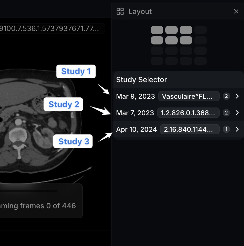
Often you may want to move between two pre-set viewing configurations. For example, between a large 3D view and a view of all projections - Sagittal, Coronal, and Axial. You can accomplish this by creating multiple layout tabs.Study Selector
As of version 1.1.2, RedBrick AI allows you to add an extra layer of verticality to your studies in the Annotation Tool. If you have uploaded Series that share a commonStudyInstanceUID, the Study Selector will display each Study in the righthand Context Panel for ease of browsing and selecting the scans you need while configuring your layout tabs.
Simply click on a DICOM Study to expand a list of its associated Series.
The Study Selector will also display the Study Date (0008, 0020) to further enable ease of searching scans by time point.
Command Bar
RedBrick AI’s Command Bar is an app-wide pop-up interface that provides a comprehensive list of all available functions and keyboard shortcuts. You can access it by pressingCMD+K (MacOS) or CTRL+K (Windows).
In the Dashboard, the Command Bar can be used to easily reference your custom shortcuts and navigate between Projects and Workspaces.
In the Editor, the Command Bar also allows you to access several other lesser-known tools and features, such as:
- Manual Backup - download all of the data associated with the current Task, AKA the “emergency backup” button
- Prune Segmentations - delete all segmentation Entities that do not have masks on the canvas
- Toggle Comment Pins